synopsis.
"The power she stole was forged in forbidden rites. Starved in wires. Now loose in flesh."
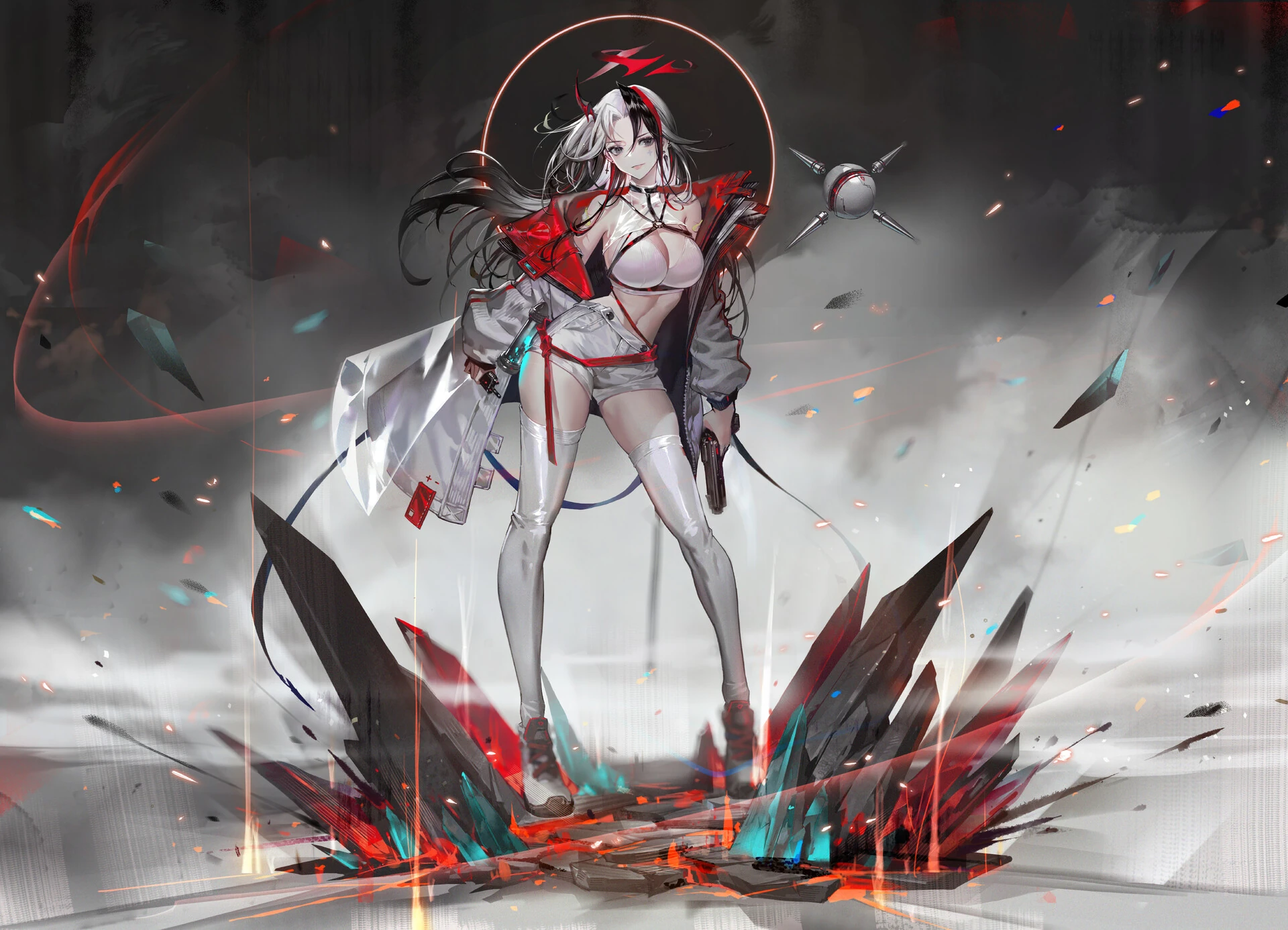
Crimson Heist is an Arcane-inspired film created by a team of seven DigiPen Bachelor of Fine Arts students about a thief who breaks into a lab and gets more than what she bargained for.
Crimson Heist is an Arcane-inspired film created by a team of seven DigiPen Bachelor of Fine Arts students about a thief who breaks into a lab and gets more than what she bargained for.
timeline.
6 months
software.
Unreal Engine 5 • Maya • Blender • Substance Painter • Clip Studio Paint • Python
DaVinci Resolve
DaVinci Resolve
team.
Lowell Chong
•
Director, Technical Artist, Editor
•
Producer, Technical Artist, Animator, Audio
•
Environment Concept & Texture Artist
•
Character Concept & Texture Artist, Animator
•
Storyboard Artist, Animator, 2D VFX Artist
•
Assistant Rigger & Animator
•
Rigger, Animator
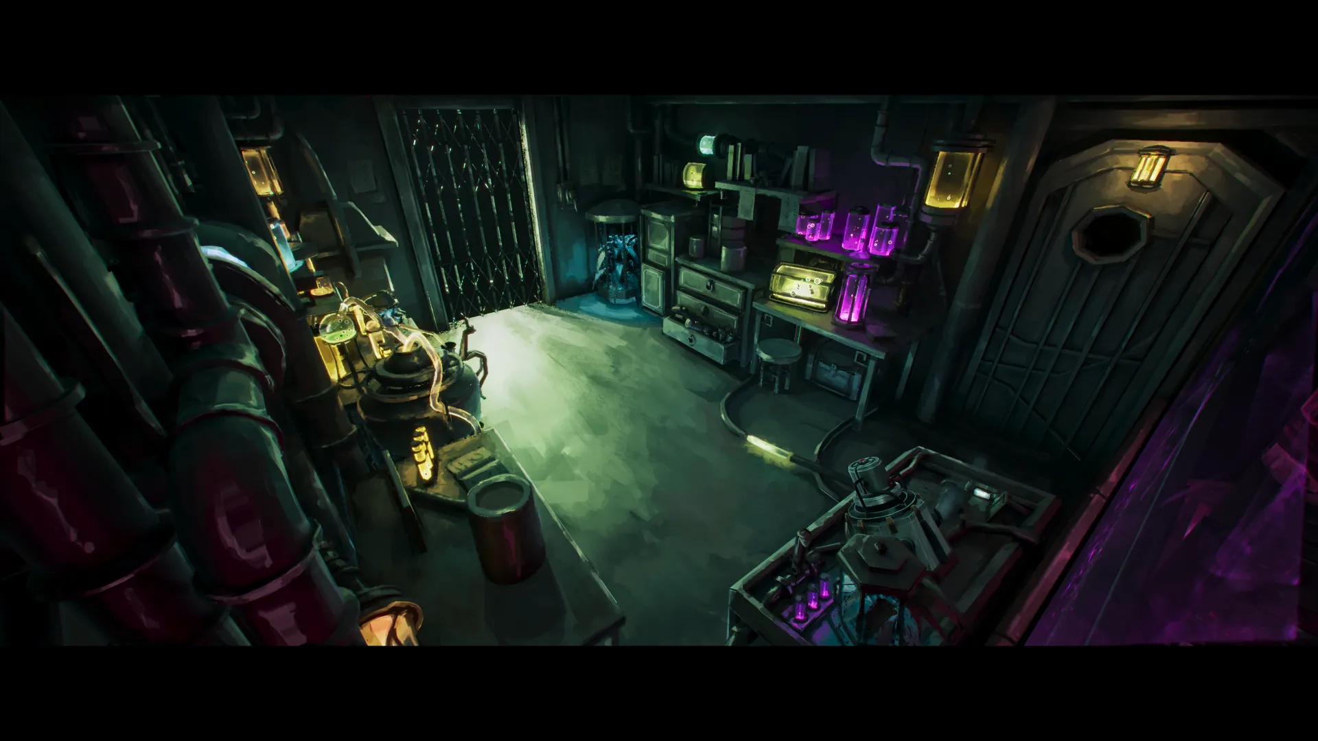
upper lab
planning.
This was a long-running group assignment, with the only requirement being to deliver a cinematic within 6 months. The cinematic's content was left up to us.
Our initial goal to begin with was to create something inspirated by the "Arcane" series by Fortiche Production. The plan leading into production, condensing the storyboarding process, looked like this:
- Arcane art style
- Handpainted textures
- Realistic post-process - volumetric fog, shallow depth of field, ambient particles, halation
- 2D animated VFX
- 2.39:1 anamorphic aspect ratio (5162x2160)
- Event: Thief breaking into a building
- Theme: Chinese Steampunk
- Specific wishlist
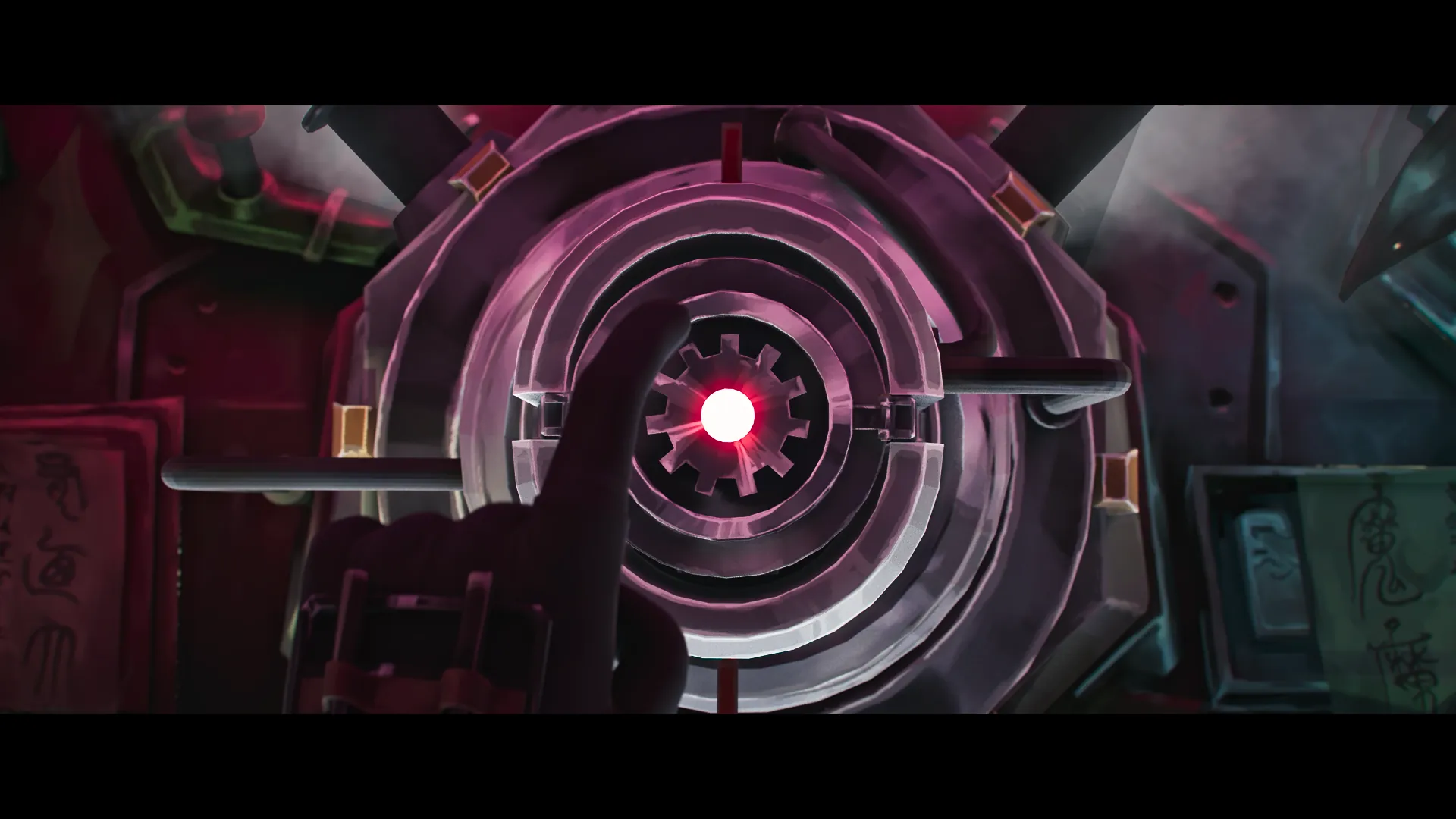
- An intricate mechanical close-up shot
- An elevator scene
- A monster-in-tube reveal inspired by Love, Death, and Robots' Sonnie's Edge
- Lab equipment from Arcane Season 2 First Look
Condensed, this presented a sizeable number of challenges to tackle on the tech side.
- Handpainted Textures
- The characters’ textures were fine to be painted the normal way (in Substance Painter) since they would be present and moving in multiple shots.
- However, creating a large number of props would not be feasible with the traditional, manual method of handpainting. Was there a way to streamline this process better for the environment artist?
- Stylized Water Shader
- This shader would be used for the large tube and various test tubes containing animated water.
- I decided early that a water simulation would not be feasible, due to the risk of adding too much render time, and I was skeptical that it would fit the style in the first place.
- At the same time, the water would be seen from the top AND side, which prevents me from using a simple SingleLayerWater shader.
- Niagara VFX (Dynamic Fog, Bubbles)
- It looked like a mix of 2D and 3D fog was used in the series. Bubbles would be time-consuming to draw manually, so it was delegated to Niagara too.
- 2.5 environments
- 2 characters
Once our overall goals were set, we started on the storyboard. I had written the story draft early on, then worked with the storyboard artist to create the actual storyboard while the other team members worked on concept art and tech research.
For concept art, please visit my team members' artstation posts for character and environment concepts!
anamorphic.
In recreating the cinematic feeling present in Arcane, I surmised that the wide anamorphic ratio played a key part in it. I also just wanted to try it out for fun :)
Since Unreal Engine was where the cameras would end up, I started configuring camera settings there. I started with a full frame DSLR configuration, then scaled up the sensor width of 24mm by 2.39 to get 57.36mm.
I managed to match it in Maya by changing the sensor size to match.
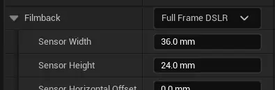
unreal starting with full frame dslr
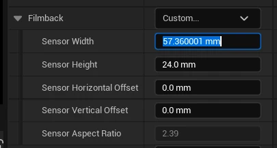
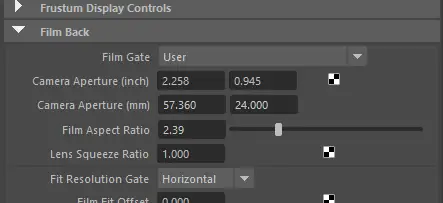
However, we faced difficulties in matching the aspect ratio of Blender cameras, which proved to be an obstacle for camera projection in Blender until we found the Maya projection method.
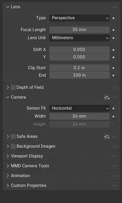
blender camera settings
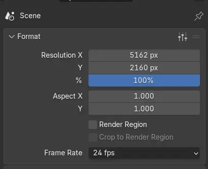
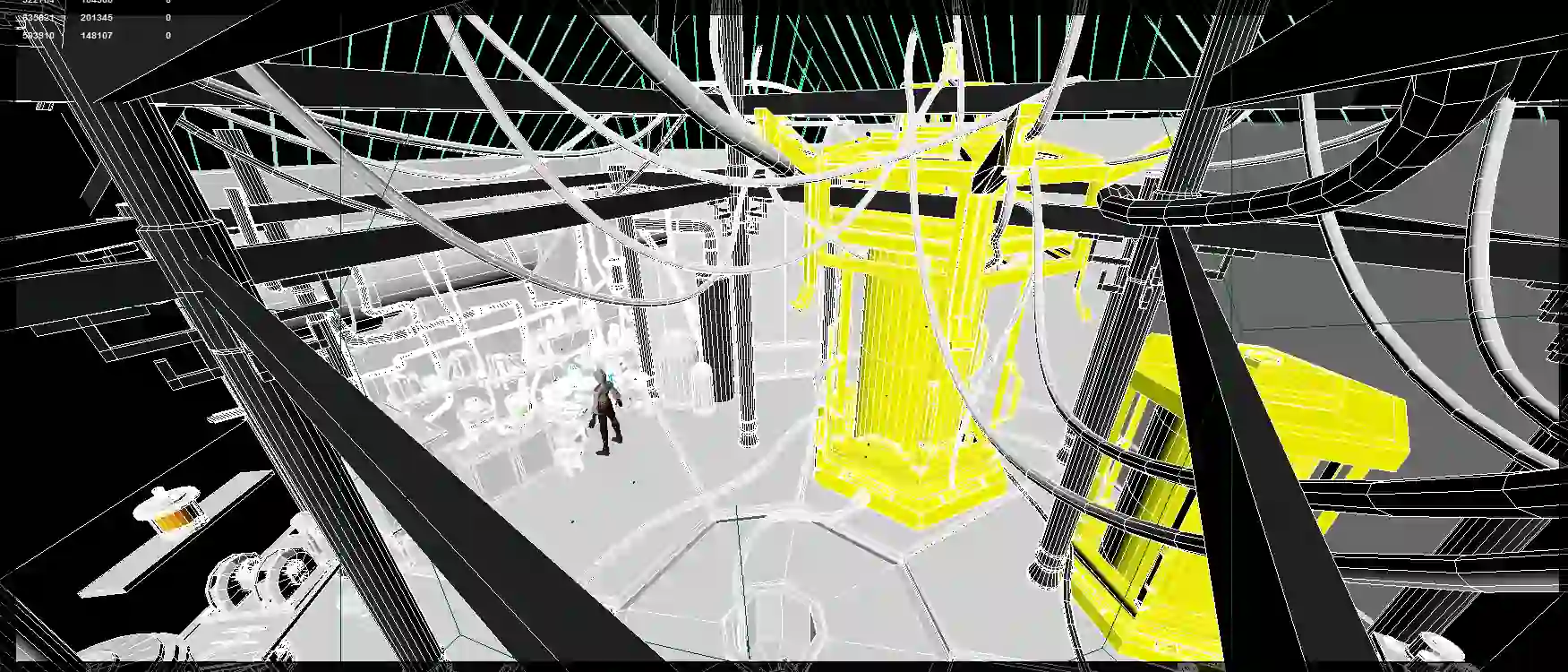
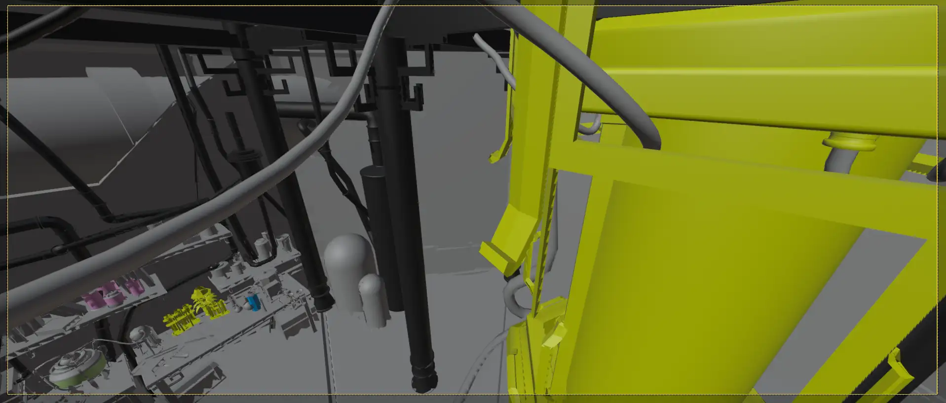
Had we been able to match the cameras between Blender and Unreal, we would have been able to texture paint using the Blender-Clip Studio method.
shots.
As a quick note, the 3D blockouts done by Wen En and cleaned up by Jonathan can be found here and here!
Once the storyboard draft and 3D blockout was done, I translated the storyboard panels into animated camera shots in Maya, with the Sequencer driving the cut timings.
This included rudimentary animation for the character so that the character's general position on the camera could be visualised.

for blockout purposes only - please trust me i can animate too
We ran into an unknown issue when importing cameras from Maya to Unreal Engine, which seemingly solved itself at random times. When attempting to import the camera, the imported camera would not inherit the position and rotation of the exported camera, and would just be spawned at the origin.
Googling for a solution did not yield anything useful, but through trial and error, we found that the Maya camera needed to be in the outermost layer of the outliner, i.e. not nested within another object or group.
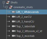
grouped camera
However, I wanted to keep the cameras grouped for cleanliness' sake, so I just moved the camera(s) out of the group when I wanted to import them.
I was a bit tempted to create an export script for this, but I decided that it wouldn't be worth the time at all.
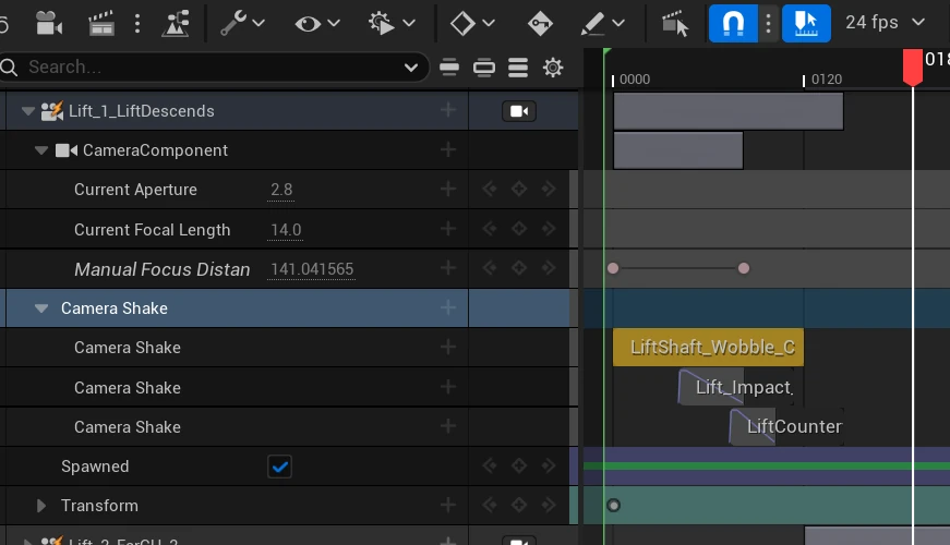
Much later in Unreal, I used a blueprint to add camera shake in instances where I wanted to simulate handheld shakiness or an impact.

camera shake - wobble

camera shake - impact
I insert the blueprint as a track in the Sequencer, under the camera I wanted to add the shake to. In each blueprint instance, I tweaked the Amplitude, Frequency and Timing to create the type of camera shake I wanted.
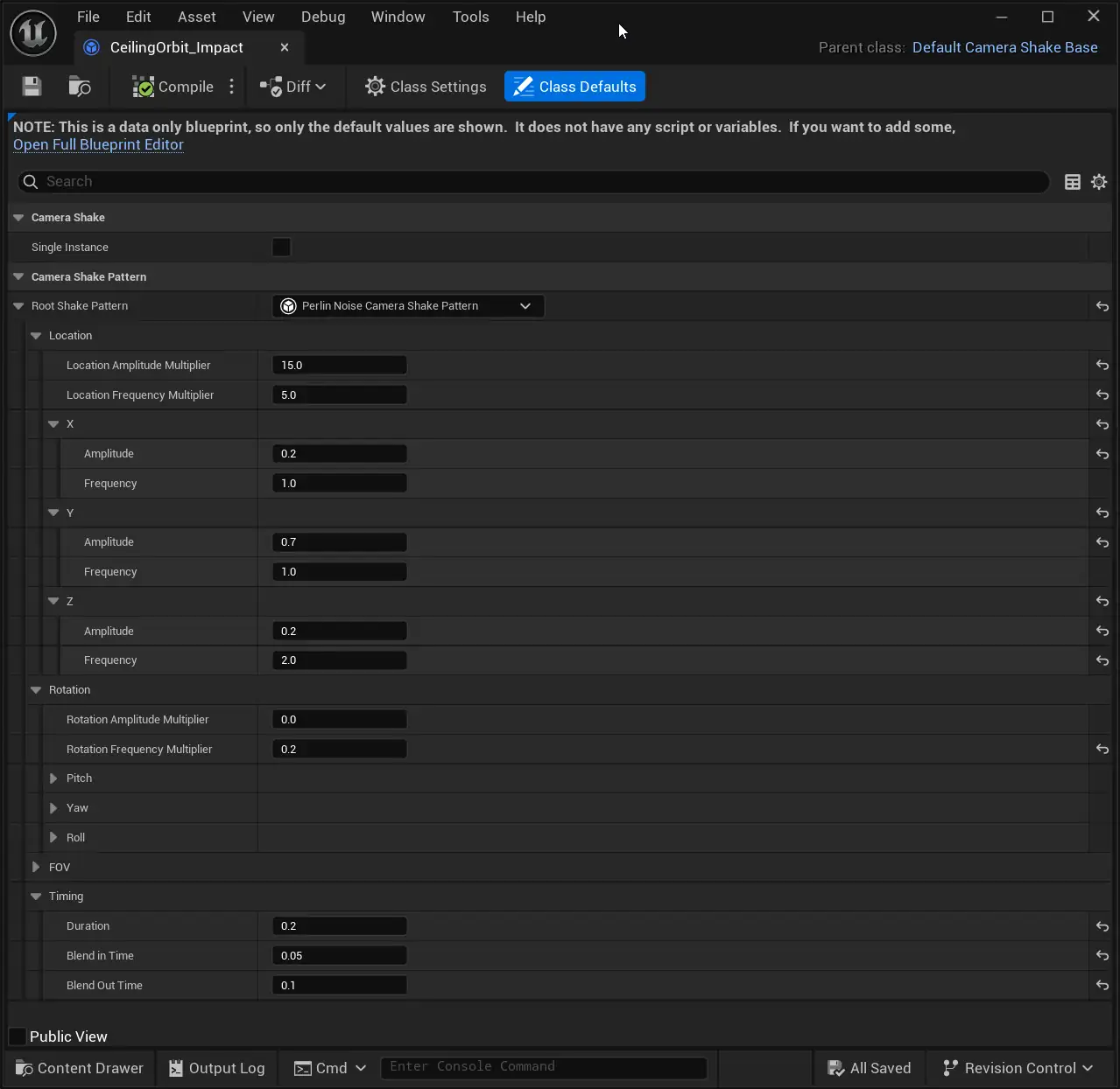
camera shake blueprint
unreal lighting.
After the 3D blockout was done, I started with the first lighting pass in Unreal Engine as I completed and imported the Maya shots.
For this first pass, I used a generic gray material with 0.5 roughness, and let the lighting add colour to the environment. I kept it somewhat simple at the start, using point lights in the tanks and a large area light for underglow.
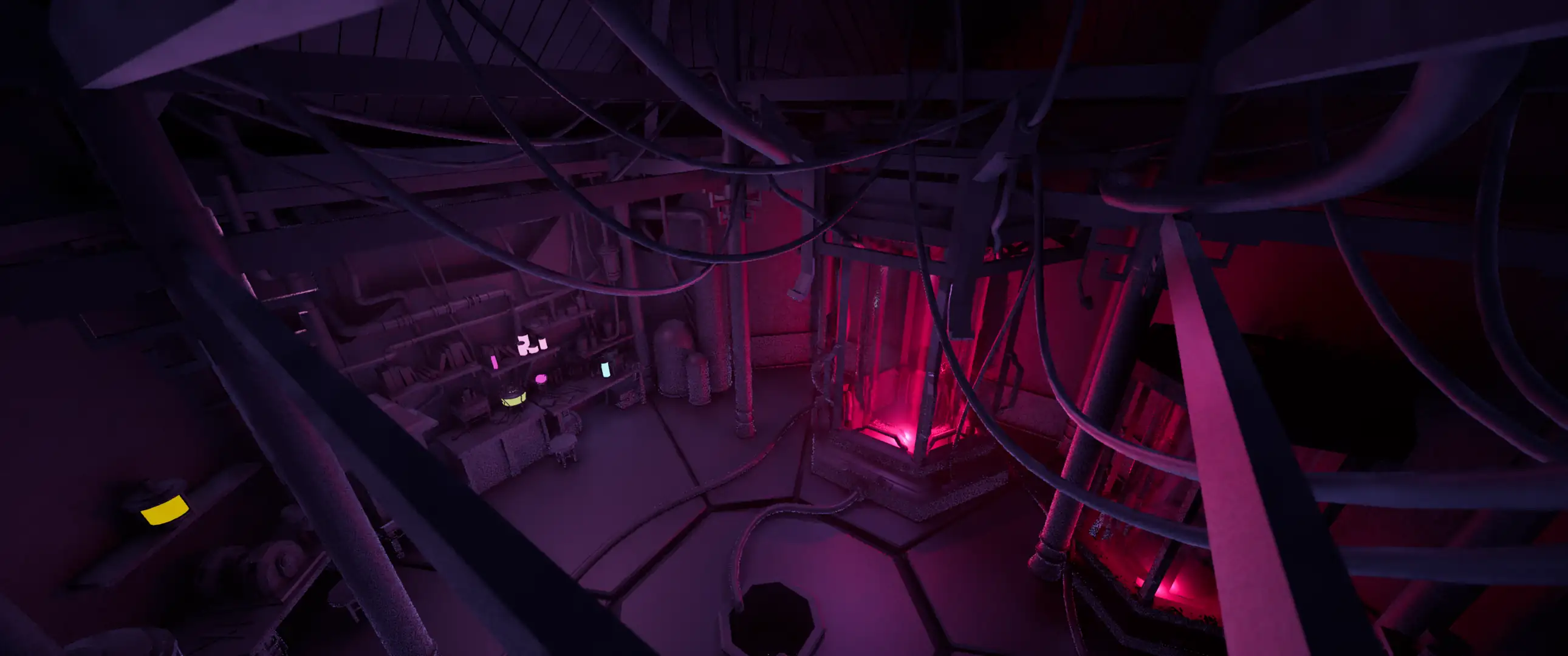
first lighting pass
After the texture was created, the first lighting pass was essentially baked into the texture, so reusing the same lighting setup didn't look right. The baked texture also tended to lean a bit darker than the actual painting, so it needed to be brightened a bit.
I turned off the first pass and did a second lighting pass. Here, I focused on supporting the texture instead by brightening areas of focus and tweaking colours. I also reused the underglow area light from the first pass but with a higher intensity.
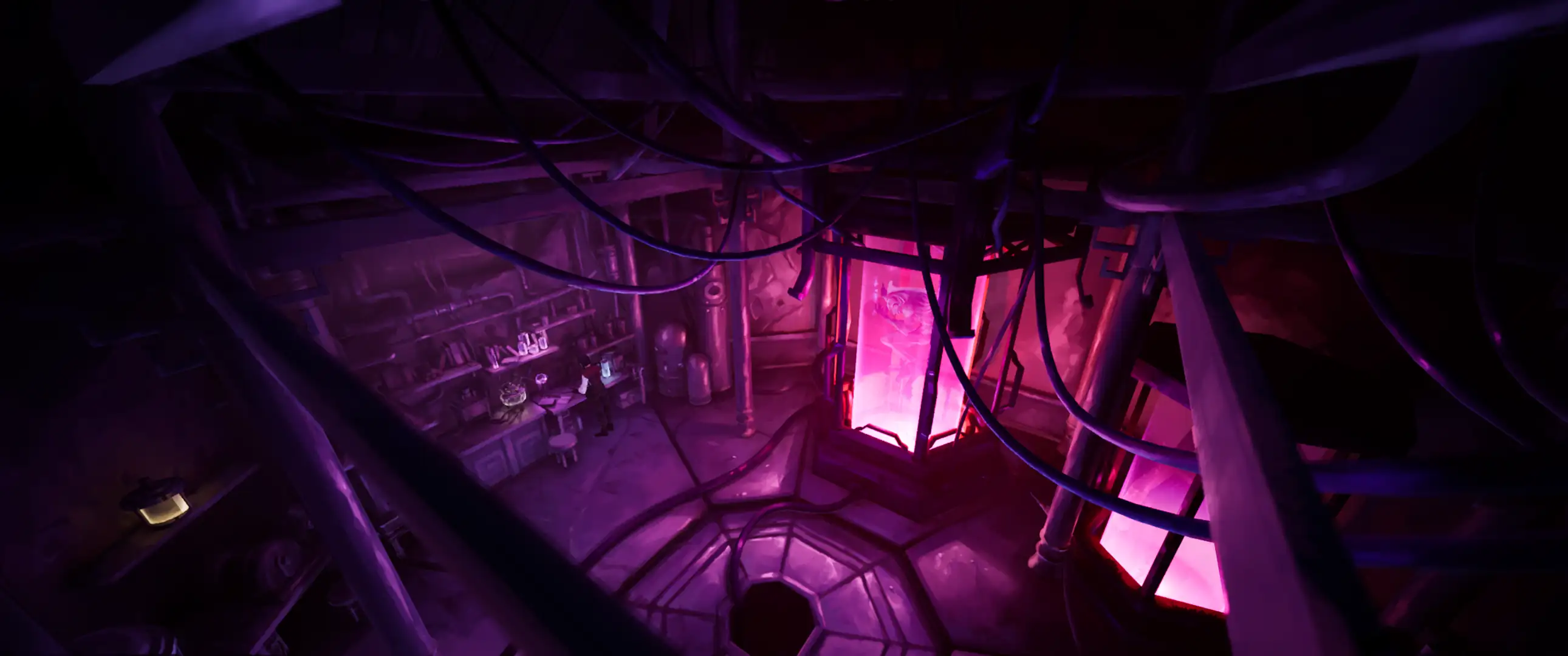
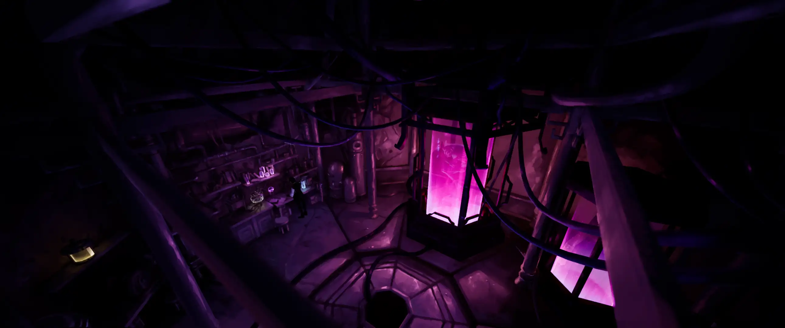
before
after
second lighting pass
Once the character animation files were imported, I also further refined how the lighting fell onto the character to ensure it was lit properly and deliberately.
I stuck to tried-and-true 3-point lighting, save for some diegetic lighting which added a challenge to ensure the lighting was kept believable yet appealing.
Light channels proved to be useful in this refinement process, as they allowed me to isolate lights to specific objects.
In this example, I added area lights on channel 2 to finetune the lighting on the main character without blowing out the surrounding lighting.
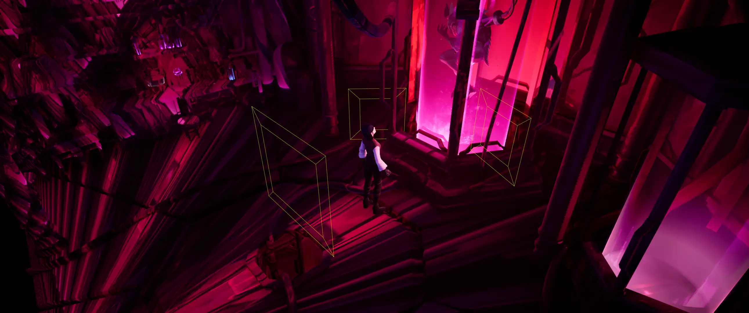
dedicated character lights
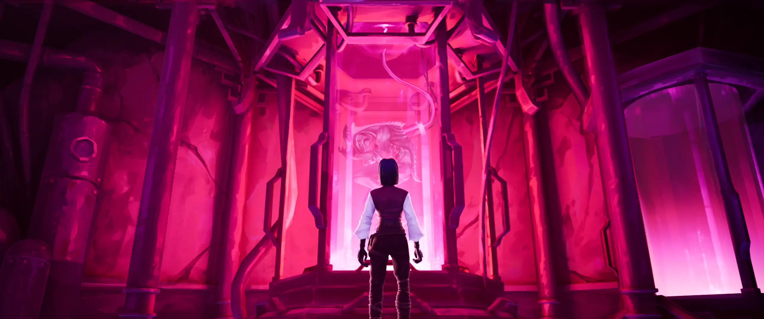
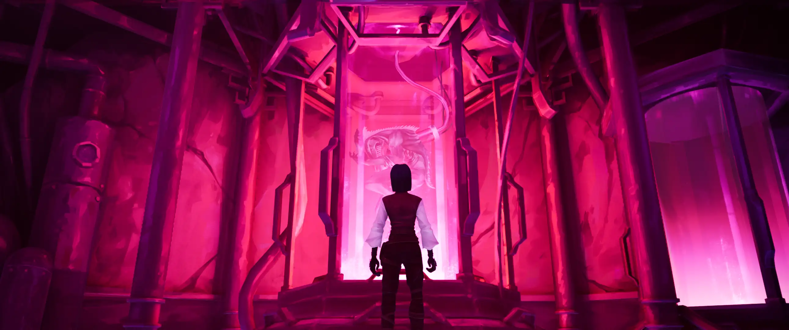
before
after
character lights in practice
shaders.
The shader used for characters and environments turned out to be quite simple. It took in a BaseColor map to be used in both BaseColor and Emissive inputs. These were finetuned using scalar parameters for Emissive Strength and Roughness.
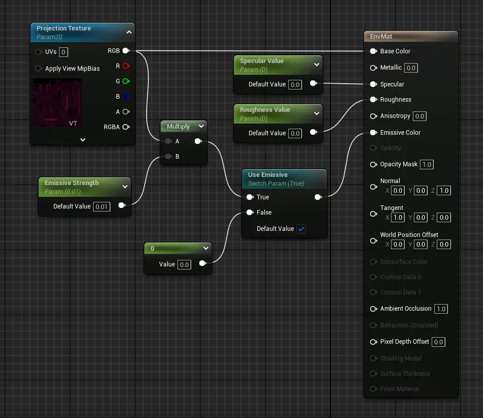
base material graph
The two environments were placed in individual materials with multiple UDIMs each. This was such that I could:
- quickly switch the material in the Unreal Sequencer
- efficiently bake the textures (covered in the projection script section)
We prioritised packing the UVs as densely as possible over tidiness, and used automatic UVs. This approach was best since there was a mountain of environment objects to unwrap, and we were going to be baking the painting onto it anyways.
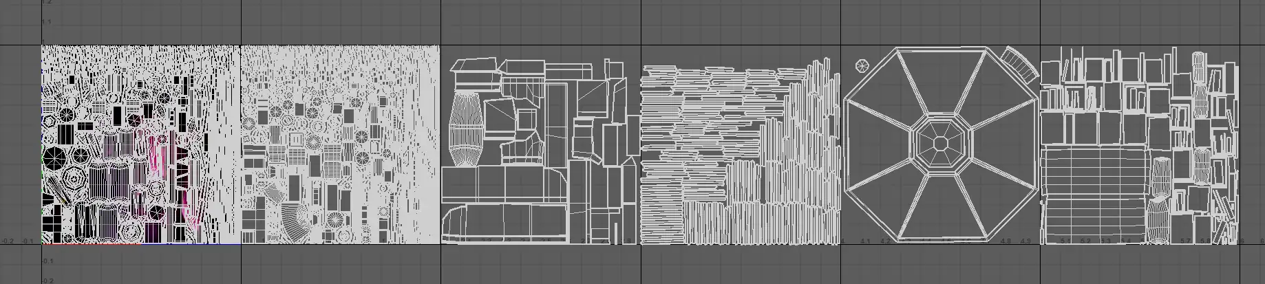
upper lab uvs
projection script.
Jonathan found that Maya was able to perform camera projection and export the resulting texture. The manual process for setting it up was as follows:
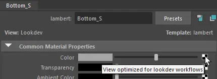
create the projection setup (1)
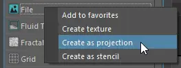


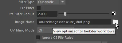
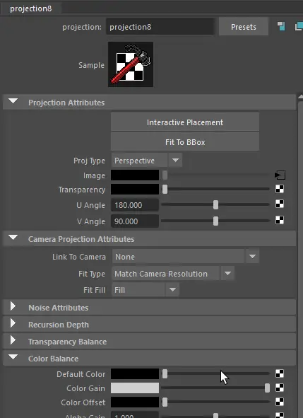
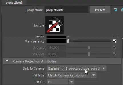
Once the projection was configured, you could move on to the actual projection step. You still needed to shift-select the target mesh and shader, then find the Convert to File Texture button in the Hypershade window, where you need to configure the settings for the export.
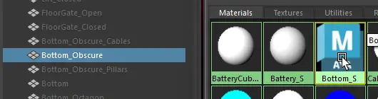
select target mesh and shader
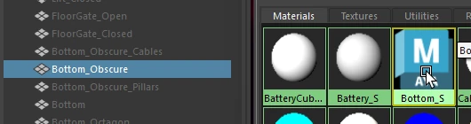
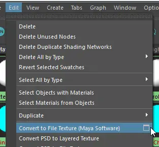
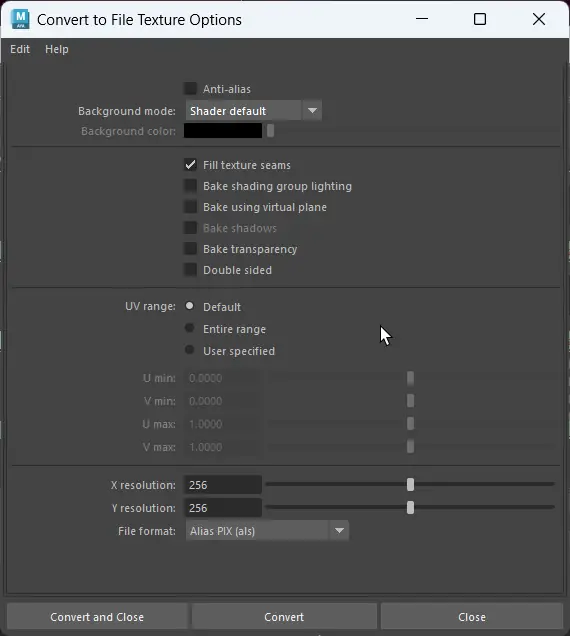
As you can see, it's a rather tedious process.
The issue we faced was that a single export was very slow due to the large resolution we were rendering it in, not to mention the setup speed. This process would need to be repeated many, many times for painting iterations, so I was very incentivised to automate it.
The main goal for the script was to directly convert the process into code, step-by-step. Most commands of the process could be found quite easily within the maya.cmds documentation, but not the export command itself.
I started by replicating the node setup process in code. This first bit is what happens when you click on the "Create as projection" button mentioned earlier.
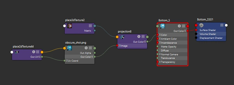
node structure goal
First, I created the material using shadingNode(), then manipulated the connections to the new material using attribute commands.
python
Afterwards, it boiled down to more connections and some editing of node settings.
python
I found this blog by Andy Davis to be very insightful during this time, and I suggest taking a look!
While I wasn't able to find a maya.cmds command for the export step, I was able to find one in MEL script by echoing the command, so I called it as is in the script using mel.eval().
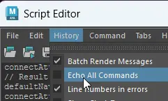
where to setup echoing
I also added a few layers of validation just in case I missed something, or if another team member wanted to bake something too.
Here's a quick example of a function validating the selected camera. To keep track of validation results, I stored them in my dataclass "LC_Projection", which I used to organise global variables like validation booleans, UI colours and filepaths.
python
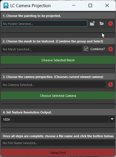
the final script ui
Another major problem that we ran into was that moving the camera or objects in the frame would break the illusion, since the texture projection only affected camera space.

texture seen in viewport
The original plan was to use Blender painting method to repaint the problem areas as they appeared in shots.
While this seemed like a perfect solution on paper, we ran into the roadblock mentioned in the anamorphic section, where we couldn't match the Blender camera 1:1 with the Maya/Unreal camera.
The second idea was to run a texture projection on the start and end of the moving shot, then blend the two images. This seemed like a sound idea at first, but I realised that I had no clue how the blending would actually be done.
The manual way would be to add the two paintings as two layers in Substance Painter and paint a difference mask by hand, but it seemed like too much of a laborious process at the time.
In hindsight, this may have been the most efficient method, had we been able to use this material for all shots in each scene, but we would lose a substantial amount of creative freedom in the process.
At the same time, it would have added several more shots to the environment artist's workload, which we could not spare.
Later on, I thought of using a mix node in Unreal to blend the two angles using camera projection as a driving mask, but I couldn't get it to work the way I wanted.
For hero objects that moved a substantial amount and weren't too large, we would get the character texture artist to handpaint the textures in Substance Painter. Objects like the battery receptable and the elevator would fit in this category.
For any other objects, we couldn't come up with a more efficient solution than going in ourselves to repaint the exposed sections in Substance Painter.
With all basic aspects of the general texturing workflow explained at this point, I can now outline the process. The process was back and forth between me and the environment artist, and looked like this:
I set up lighting in Unreal Engine, mentioned in a previous section.
I took High Resolution Screenshots of lighting, and any black/white masks required for the shot to help isolate smaller objects for painting, then sent these to the environment artist to paint over.
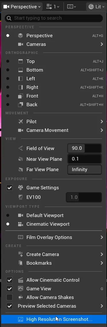
high resolution screenshot button
Once the paintover was done, I ran the projection script in Maya to generate the shot texture.
In Unreal, I imported this projected texture and assigned a keyframe on the matching shot to switch the environment's material to this new texture. I made many material instances of the base shader to do this.

keyframed material switching
One hero shot per environment was prioritised, so that the resulting projection could be used for a base for the rest of the shots in the environment.
In this example, the main establishing shot for the lab environment was used as the first base.
As touched upon earlier, I sent screenshots of the first lighting pass, along with a few black & white masks to use as clipping masks.
unreal lighting screenshot
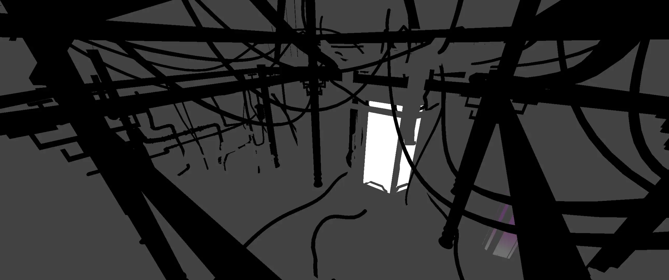
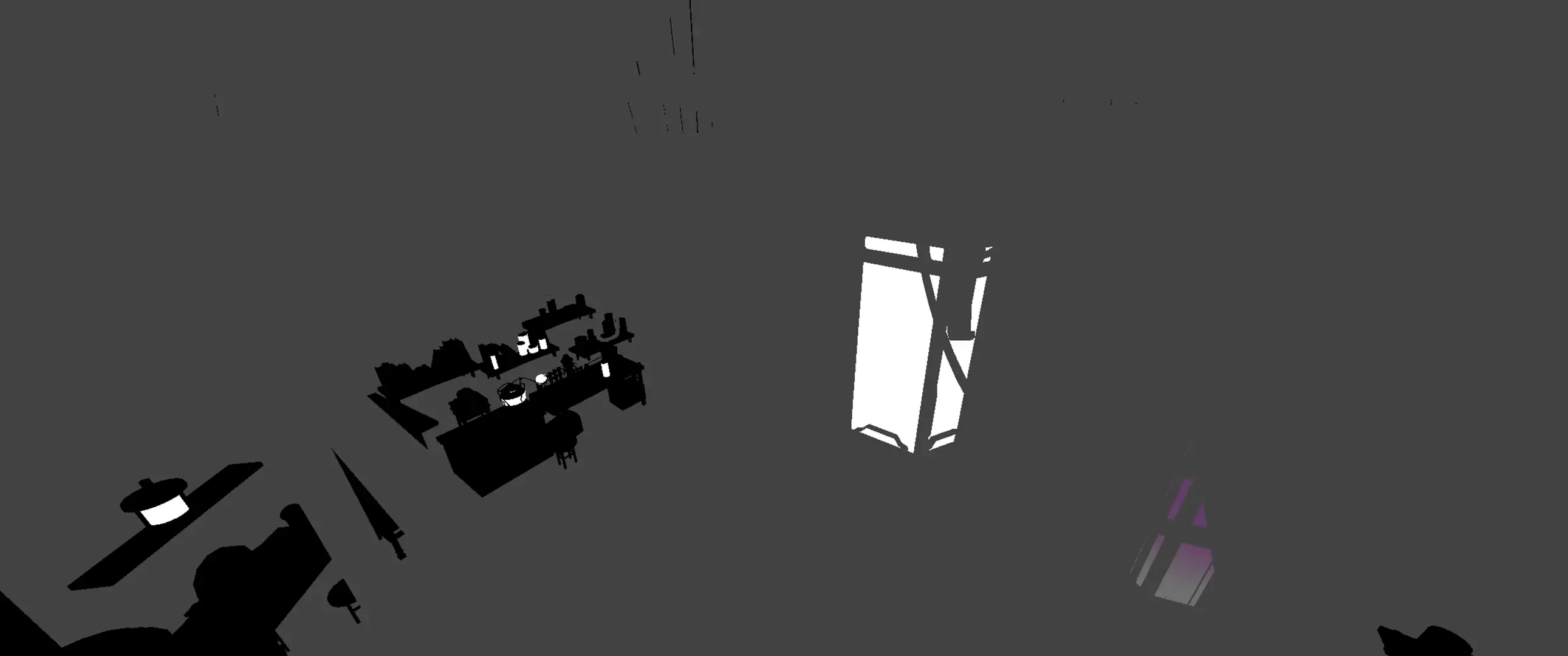
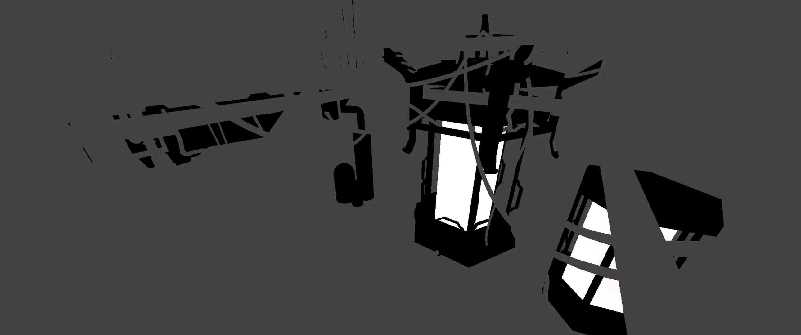
Since the projection only affected what the projecting camera could see, I needed to perform separate projections that each focus on major objects which were obscured or obscured other objects.
Thus, the painting was sent back to me with the masked objects present on separate images.
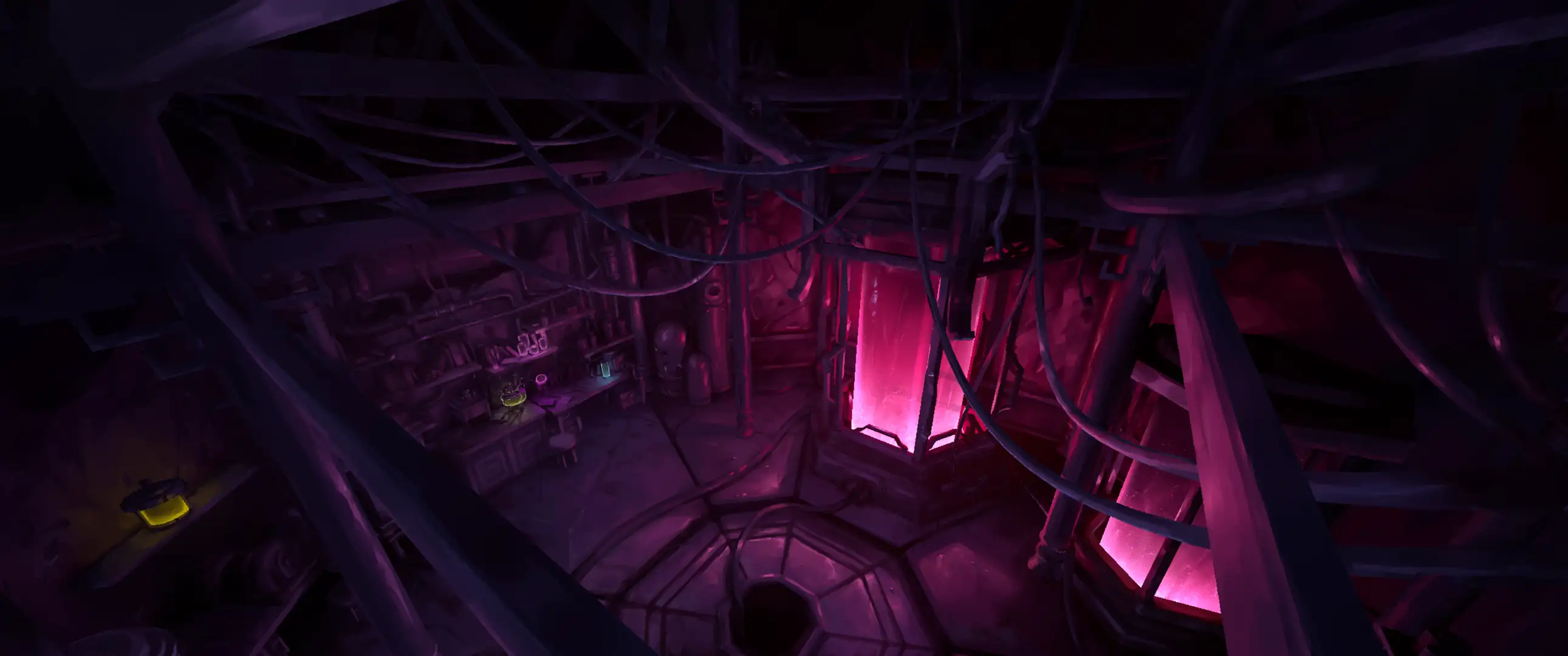
everything included
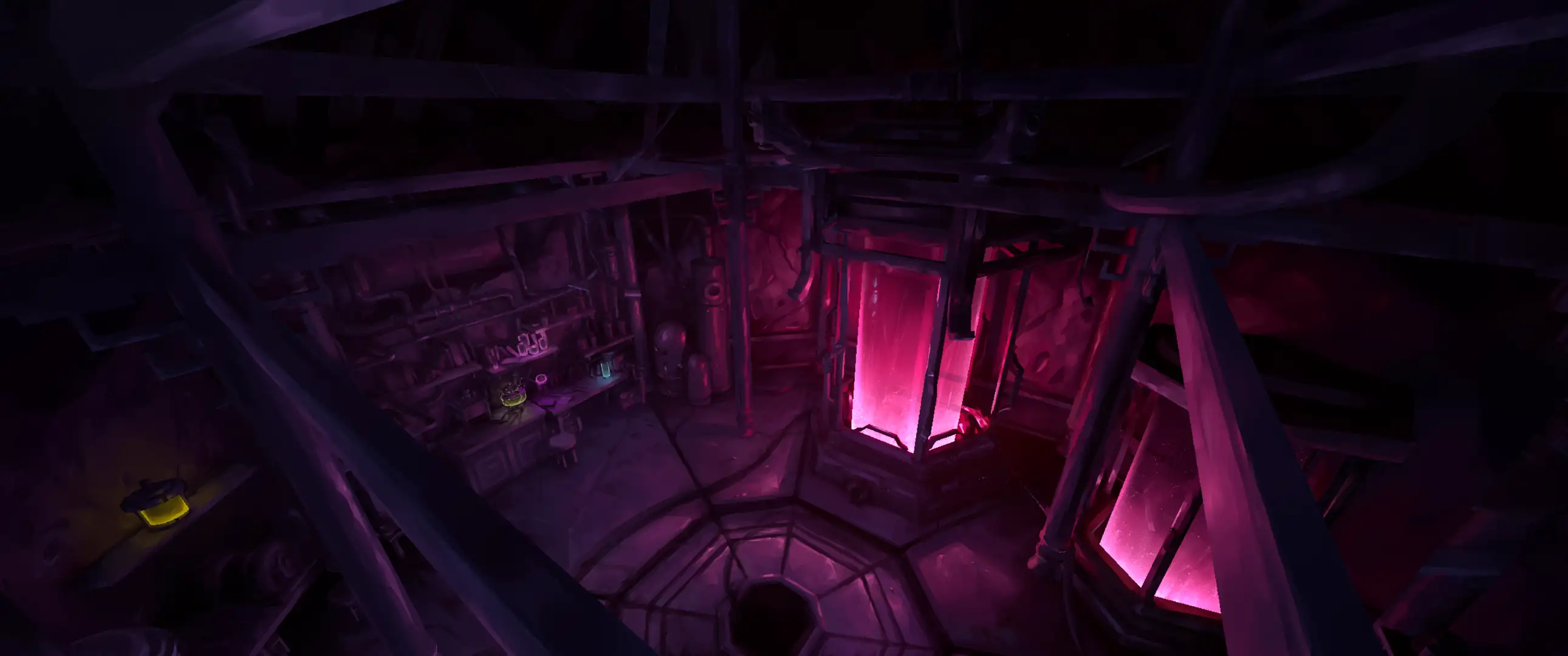
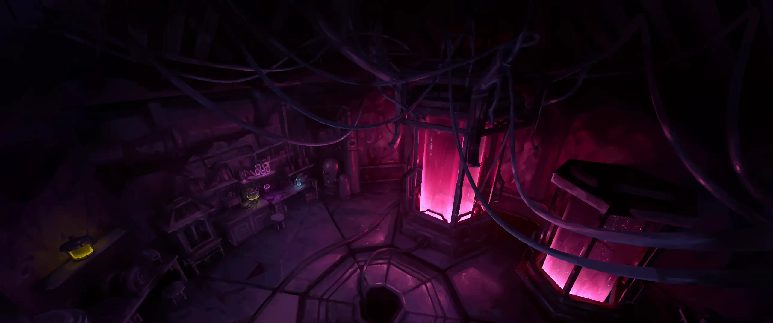
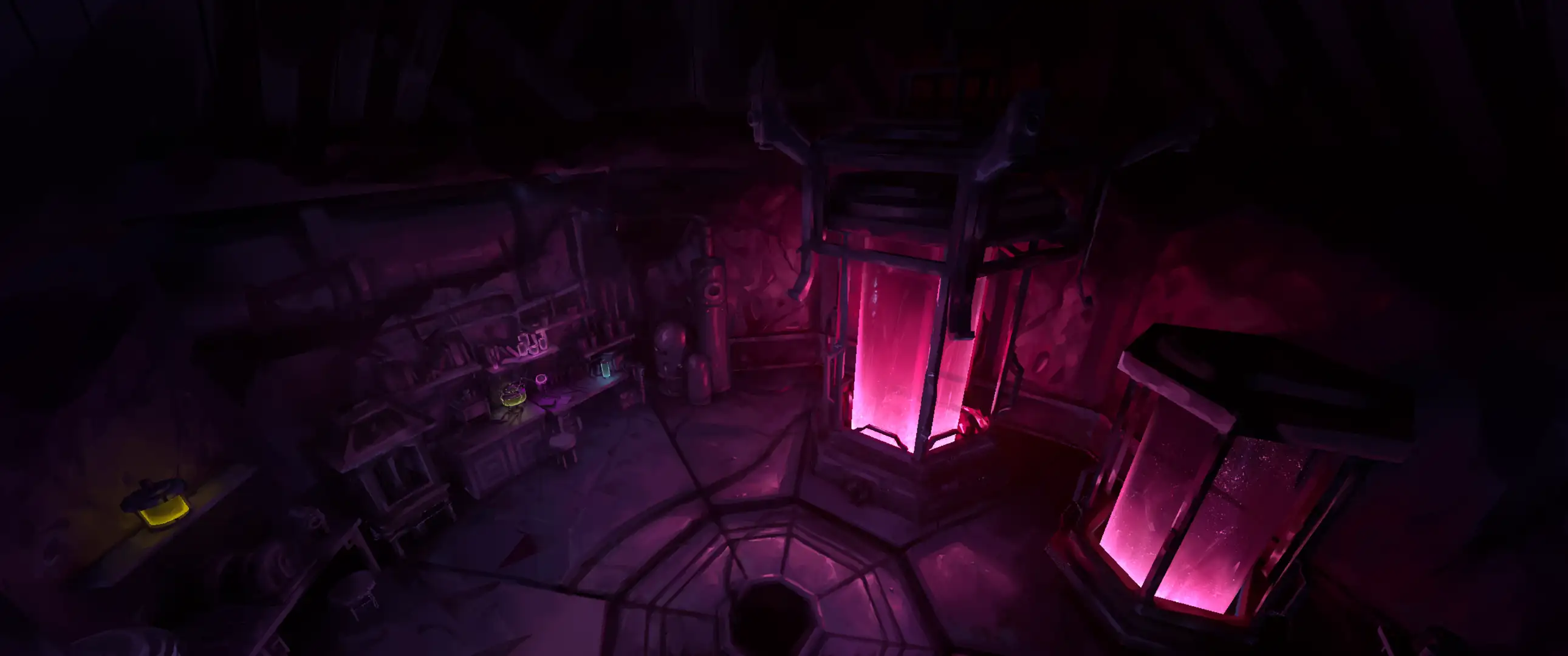
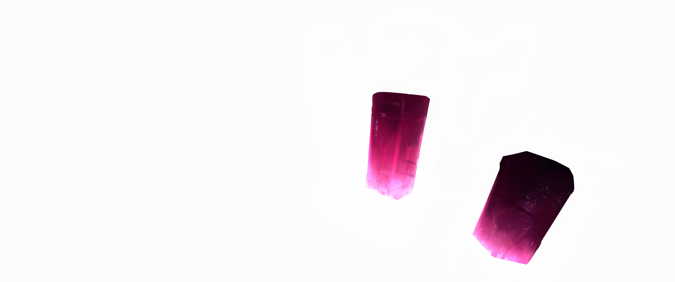
Then, I used the projection script to perform separate projections for each of the individual objects that are obscured by other objects.
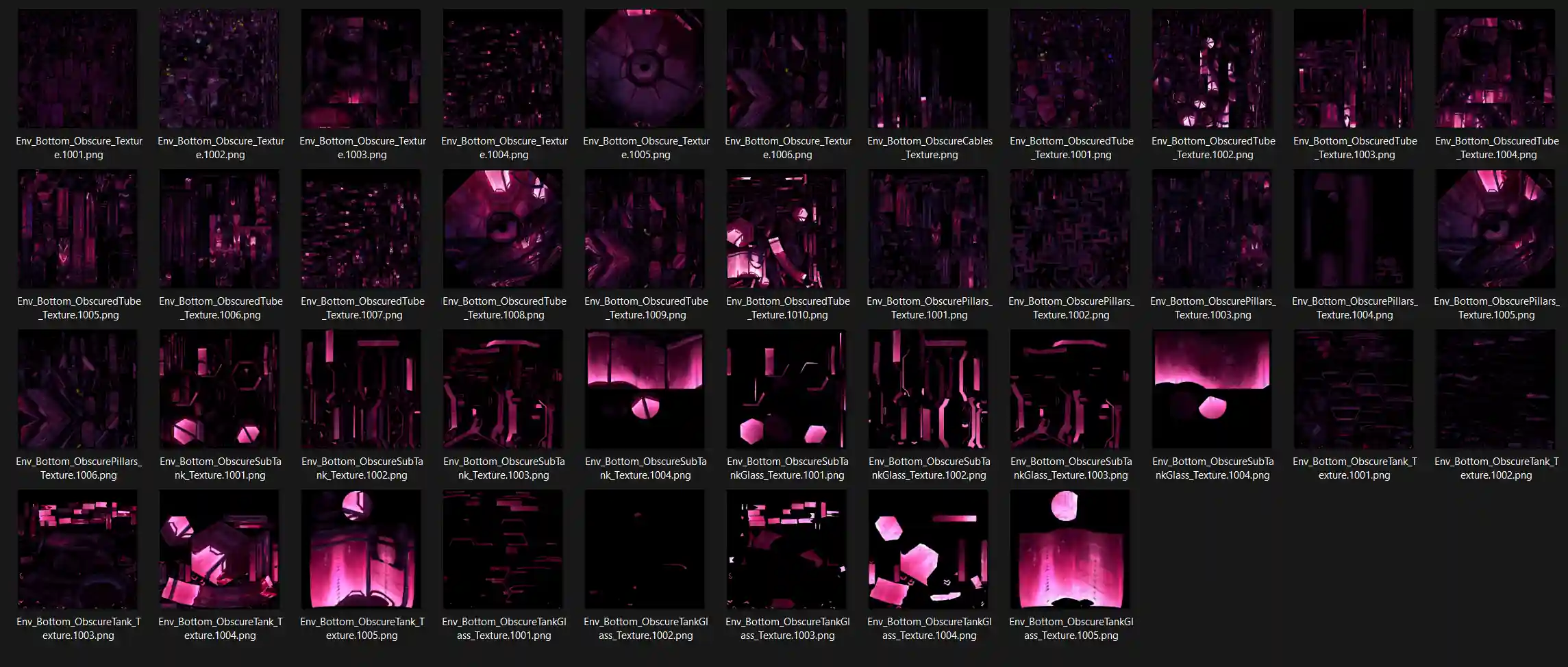
projected textures for this shot
After I imported the textures into Unreal Engine and applied them to the mesh, the colours could be loosely carried forward to help paint subsequent shots in the environment.
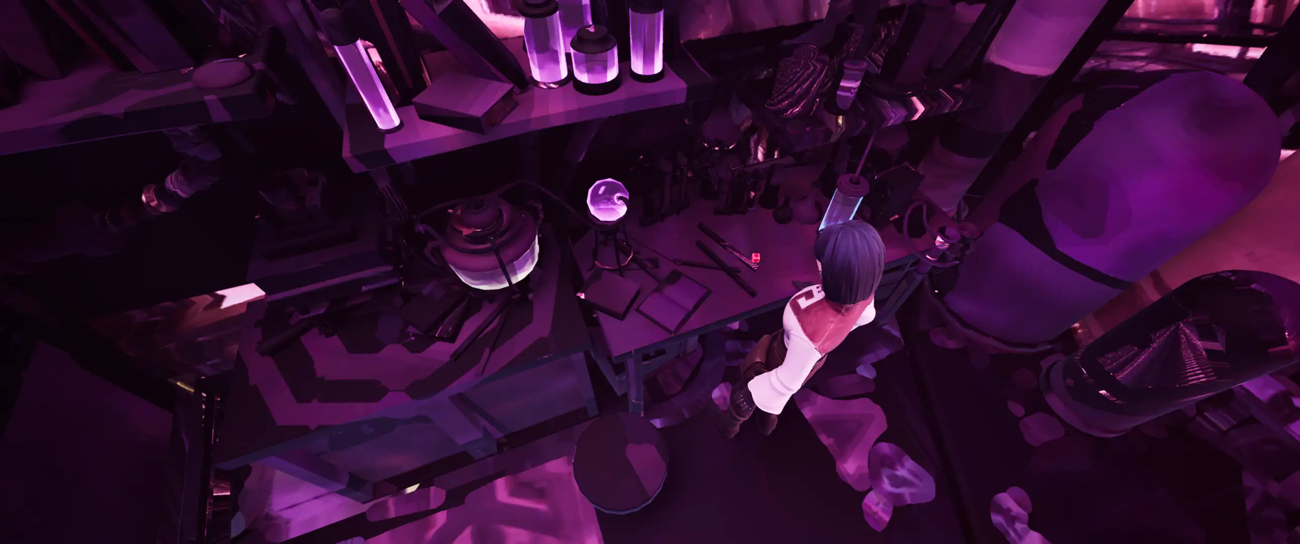
texture carried over
One hero shot per environment was prioritised so that the resulting projection could be used for a base for the rest of the shots in the environment.
It goes without saying that this process involved a lot of back and forth feedback and refinement, including shot changes midway, so the projection script ended up seeing a lot of use.
bubbles vfx.
The time came to create bubbles for the various tubes in the environment, so Niagara was elected since it was fast to create and render, and allowed for easier adjustments afterwards.
I'll start with the material behind the bubbles.
I used Niagara's Dynamic Parameters to link some of the user parameters to the material itself. This let me generate random values for each Particle System instance to add variance passively to the effect.
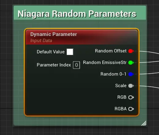
dynamic parameters
Starting with the emissive color, I added two Vector3 parameters to serve as min and max values for a color range.
To generate this range, I split the colors into their individual channels, then lerped the R and G values with a random 0-1 value as the alpha.
I appended them together with their original B values then multiplied it with a random emissive strength and the Particle Color alpha from the Particle System to get the final emissive color.
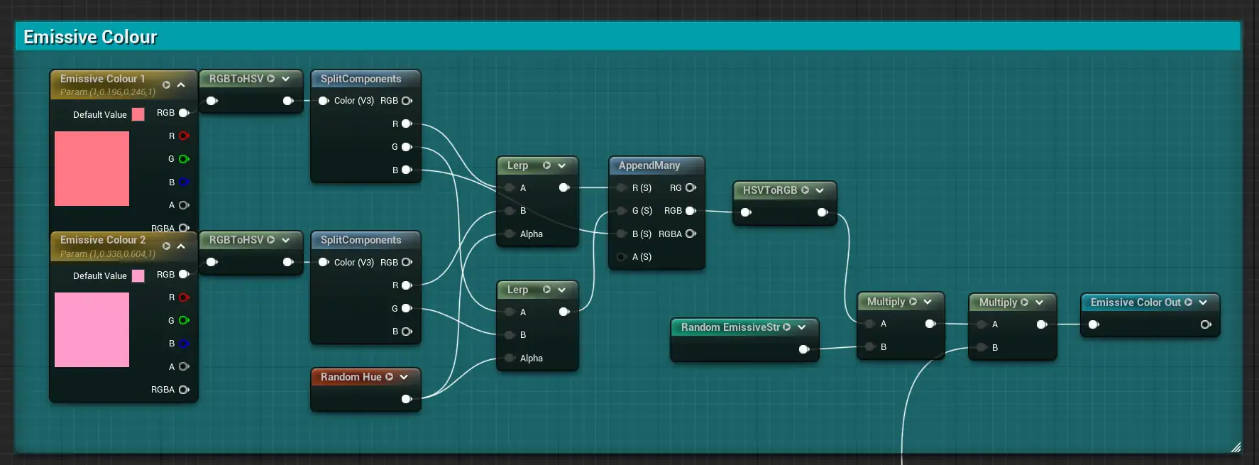
emissive color section
For the opacity, I grabbed a Fresnel node and lerped it between black and white, with black being the inside of the Fresnel.
Afterwards, I just needed to multiply that by the Particle Color alpha for the opacity. I notice now that I used the alpha to get a specular value, but I would rather set a uniform value, since it meant reflections would barely be visible around the center of the bubble.
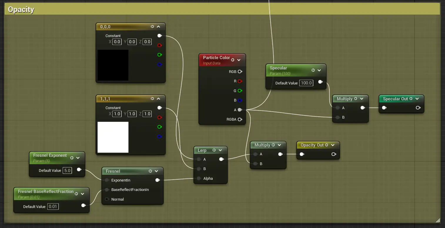
opacity section
Finally, I setup a panner, including a Random Offset dynamic parameter to vary the panning speed and location between instances.
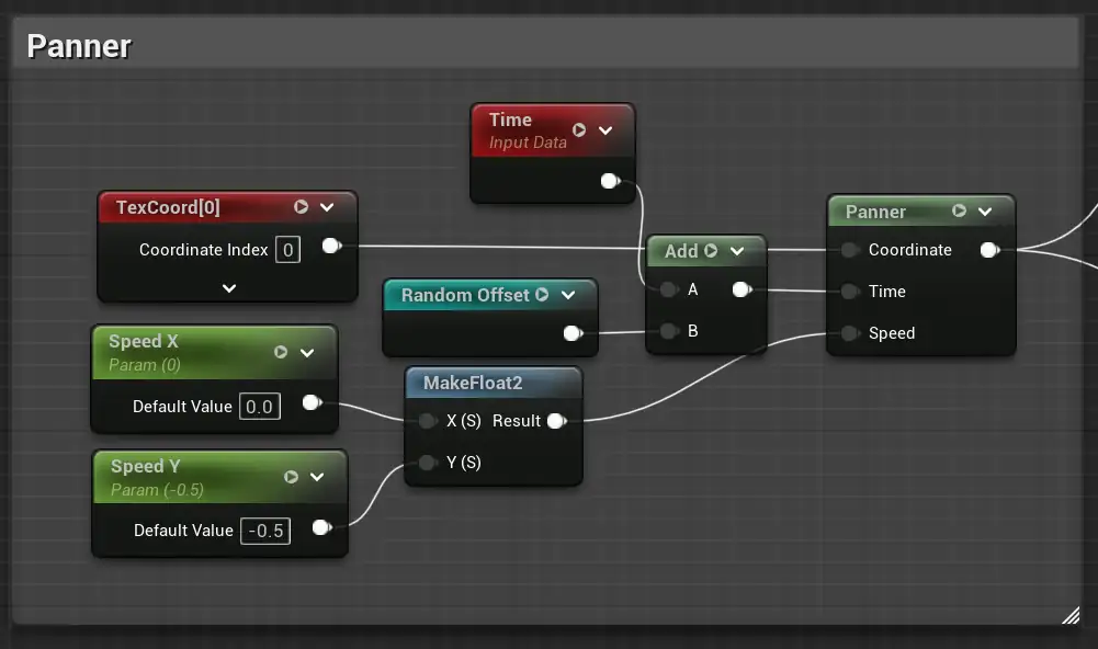
panner section
Afterwards, I applied it to a height and normal map to grab those respective values.
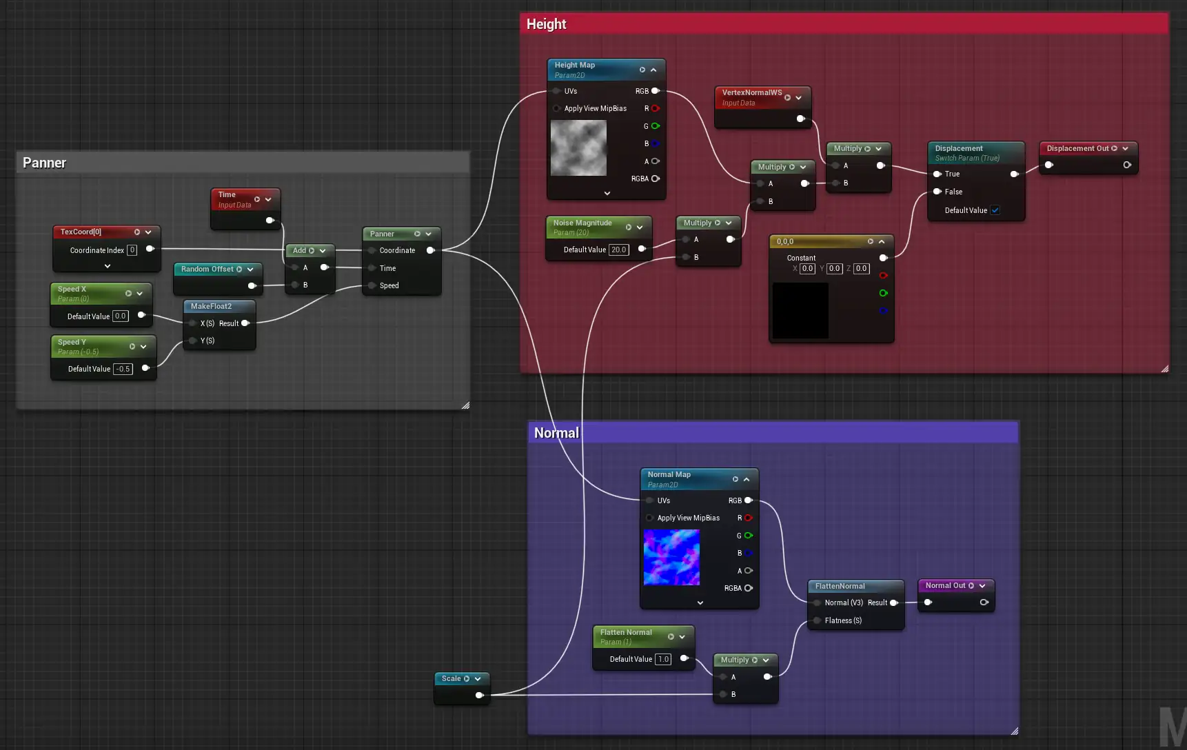
panner used for height and normals
I used named reroute declaration nodes at the end of each output path to keep the node graph tidy.
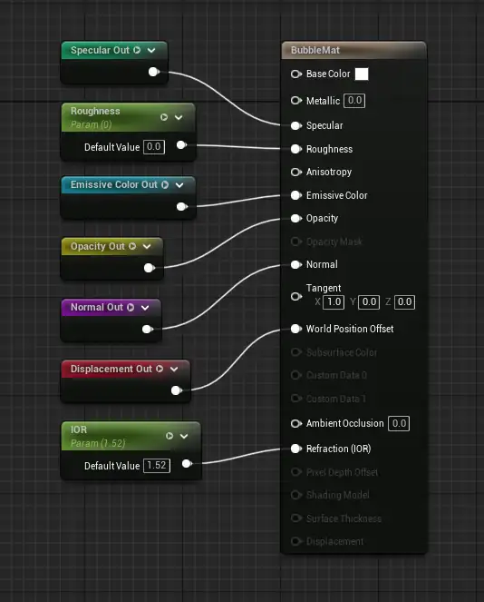
output
The bubble's material did most of the heavy lifting here. Once it was settled, I setup a simple emitter to support it. I didn't do anything fancy, so the main edits I made can be seen through the user parameters I set.
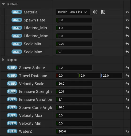
user parameters
Once this was done, the bubbles were added into the scene and tweaked manually.
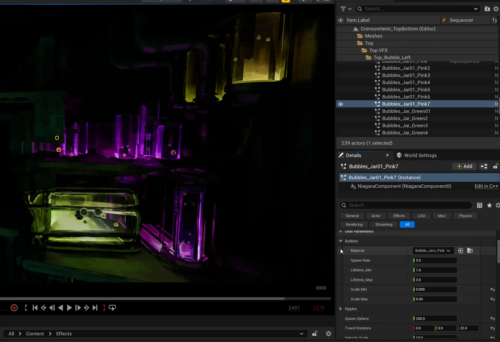
bubbles added to scene
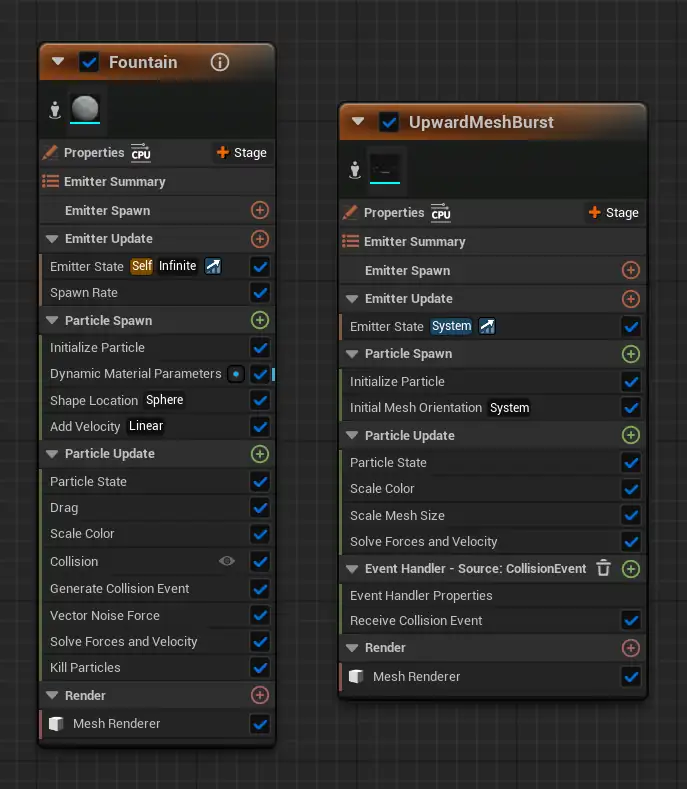
The bubbles used in the main tank had a modified version of the effect, where I used a second bubble emitter in the place of the ripple emitter. This second emitter was used to handle much tinier bubbles almost akin to water particulates, which I used a much higher spawn rate and smaller particle size for.
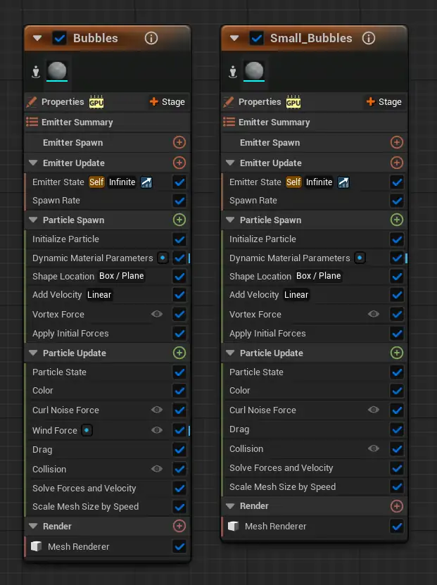
main tank version
I also put more emphasis on turbulence for the bigger bubbles using Curl Noise Force and Wind Force, so that the bubbles would move more unpredictably.
For the test tubes on the upper floor, I used this video to see how to use travelled height to destroy the bubble particles when they reached the water surface.
render.
Our rendering speed was honestly quite fast, since we were rendering on Lumen with only diffuse maps used and a pretty low polycount.
With this extra leeway, I added a 150% screenPercentage console variable to render at 1.5x native resolution and downscale back to native from there. This gave extra detail at the cost of some render time. I also turned off the denoiser here to do it in post later on.
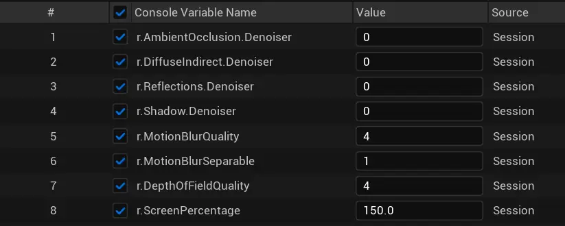
console variables
I added an OpenColorIO config to convert from Linear sRGB to ACEScg upon export, where I also disabled the tone curve here. These changes allowed for more accurate colour representation in the final picture, since direct renders from Unreal tended to be slightly different from the viewport.
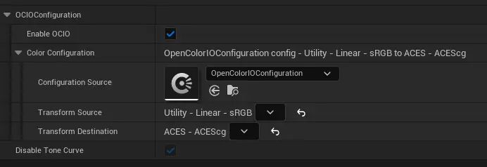
OpenColorIO (OCIO) configuration
I exported in .exr format to retain a higher bit depth for colour grading. Here's what my render settings ended up looking like.
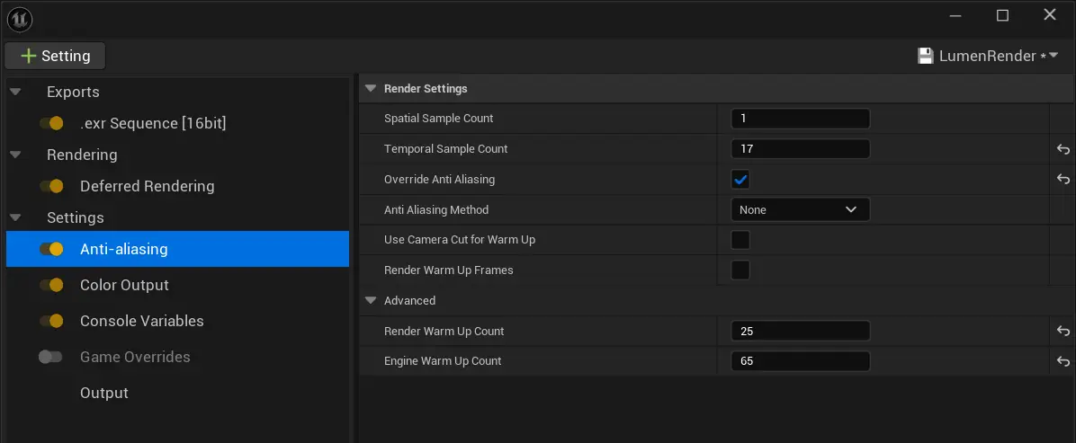
render settings
colour grading.
I watched a lot of videos by William Faucher at this time, which cover Unreal Engine lighting and rendering techniques extensively.
The main video I referred to at the time was his Unreal to DaVinci Resolve Workflow video, which covers not just the render settings you would need to think about, but also the entire colour grading process afterwards.
With the rendered shots coming in as .exr and ACEScg colour space, I select all the clips, right-click, and set their color space transform setting to ACEScg so they get read correctly.
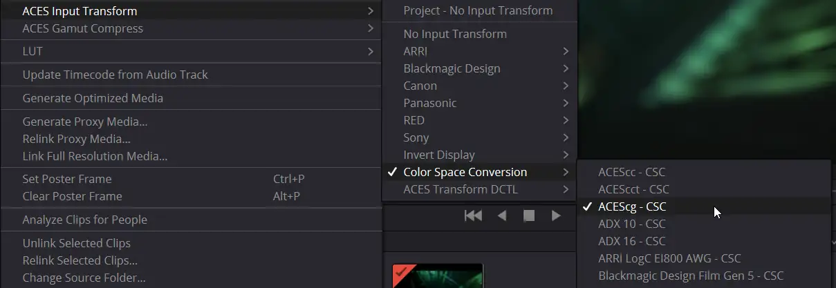
color space transform setting
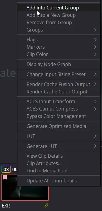
I set a flag for the clips to colour code them based on the shot, and also because I need the flag to be able to group them. This means that I can setup a single pre and post edit for the entire group for adjustments that I would want for all shots.
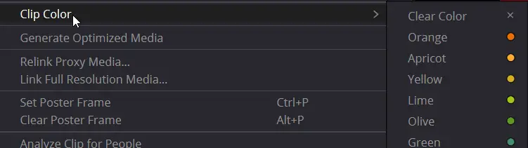
set flag
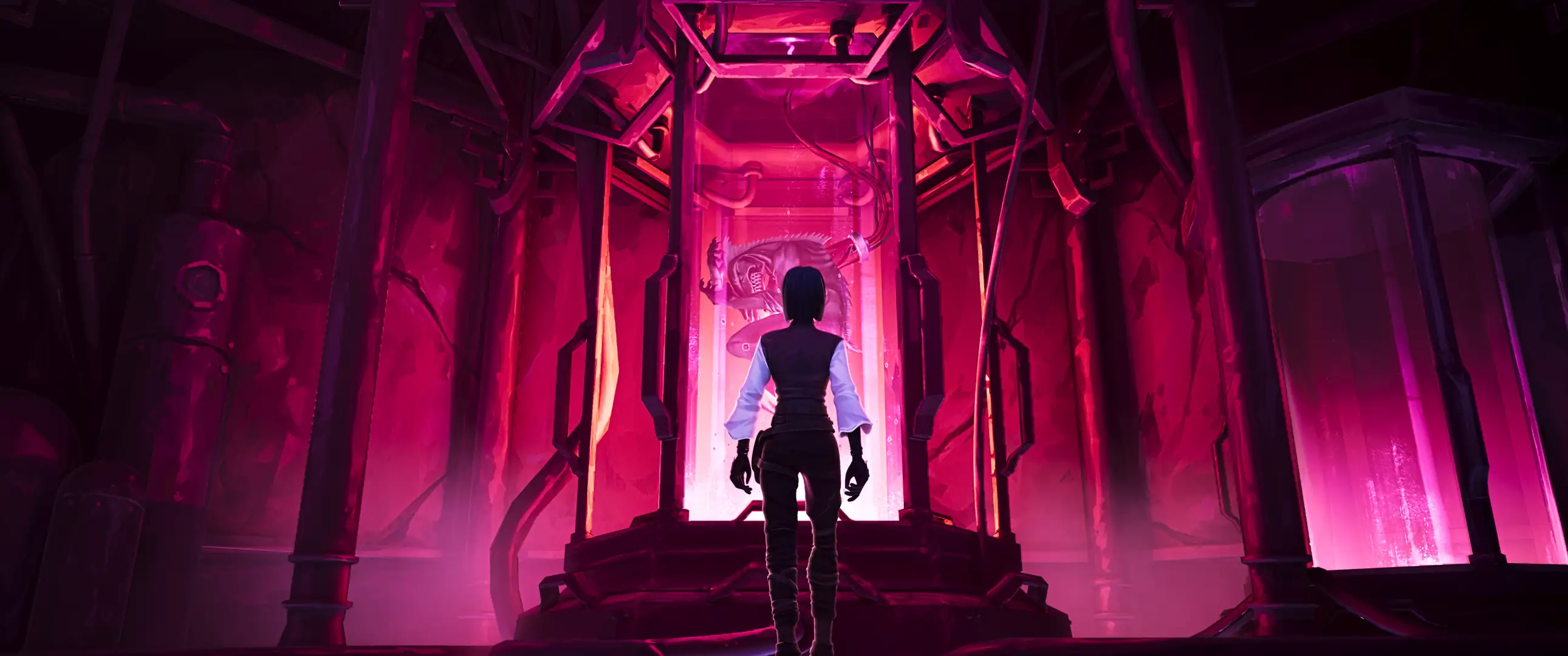
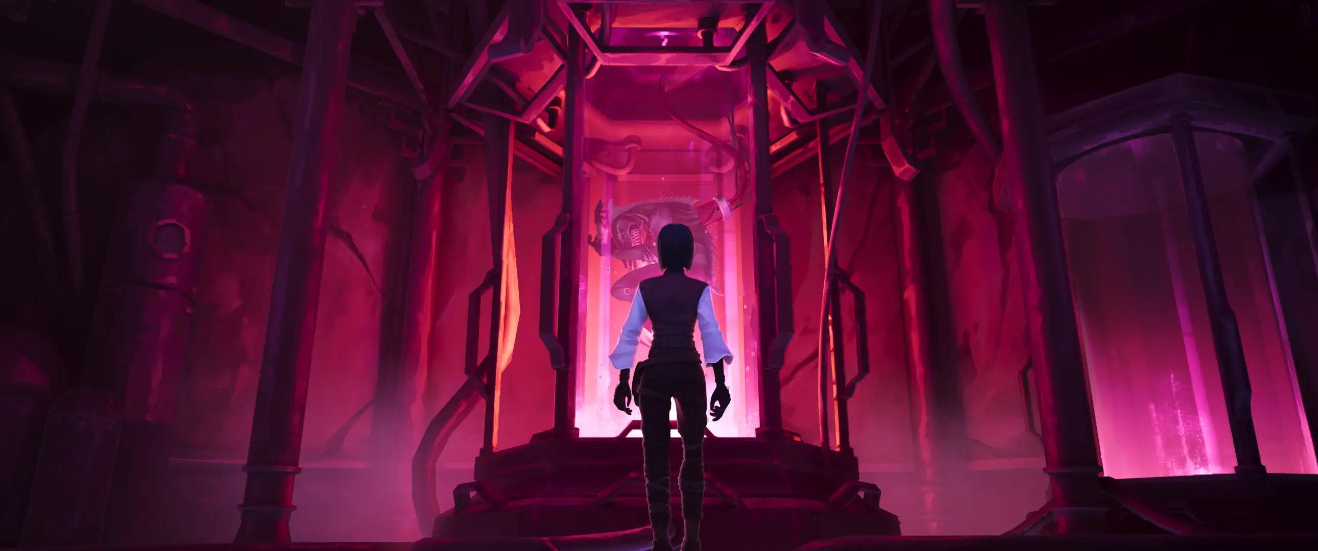
In the pre-clip section, I added a Denoise node, which cleans up some grain and lets me skimp a bit on render samples in Unreal to save time.
I also added a subtle Sharpen effect. Then, I added a correction node to use curves to exaggerate the extreme darks and lights a bit for contrast.
Finally, I added another correction node to desaturate the picture a bit.
before
after
pre-clip result
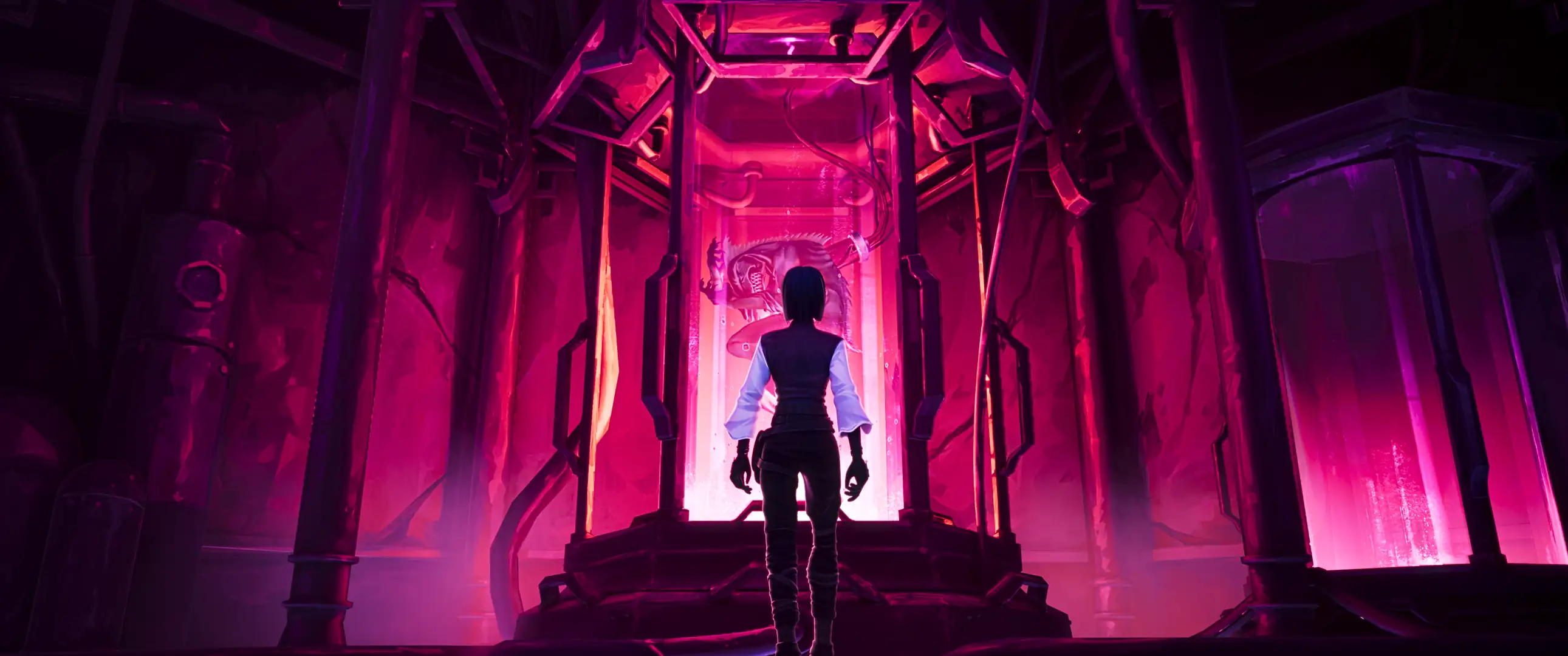
For each shot, I first added a few nodes for Values, Temperature, Shadow Color and Halation by default. I use halation instead of Unreal's bloom since it's more convenient to adjust here.
before
after
clip result
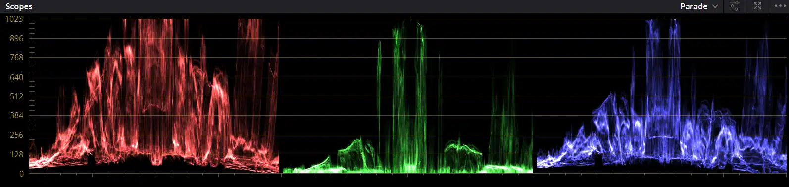
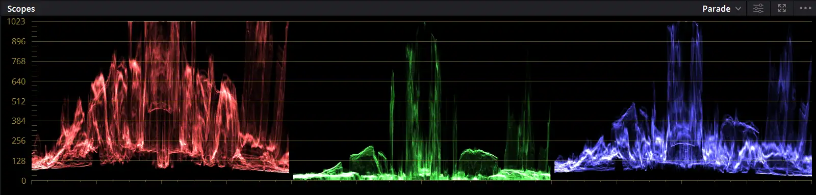
I didn't treat the settings for these nodes as one-size-fits-all solutions, but rather tweaked the values based on what I thought shot needed. I used the Parade and Waveform Scopes, and the picture itself to judge how to best edit it.
What I tried to aim for in the scopes is to fill as much of the range of values as possible, and tame any colours which were dominating the picture too much.
before
after
scopes example
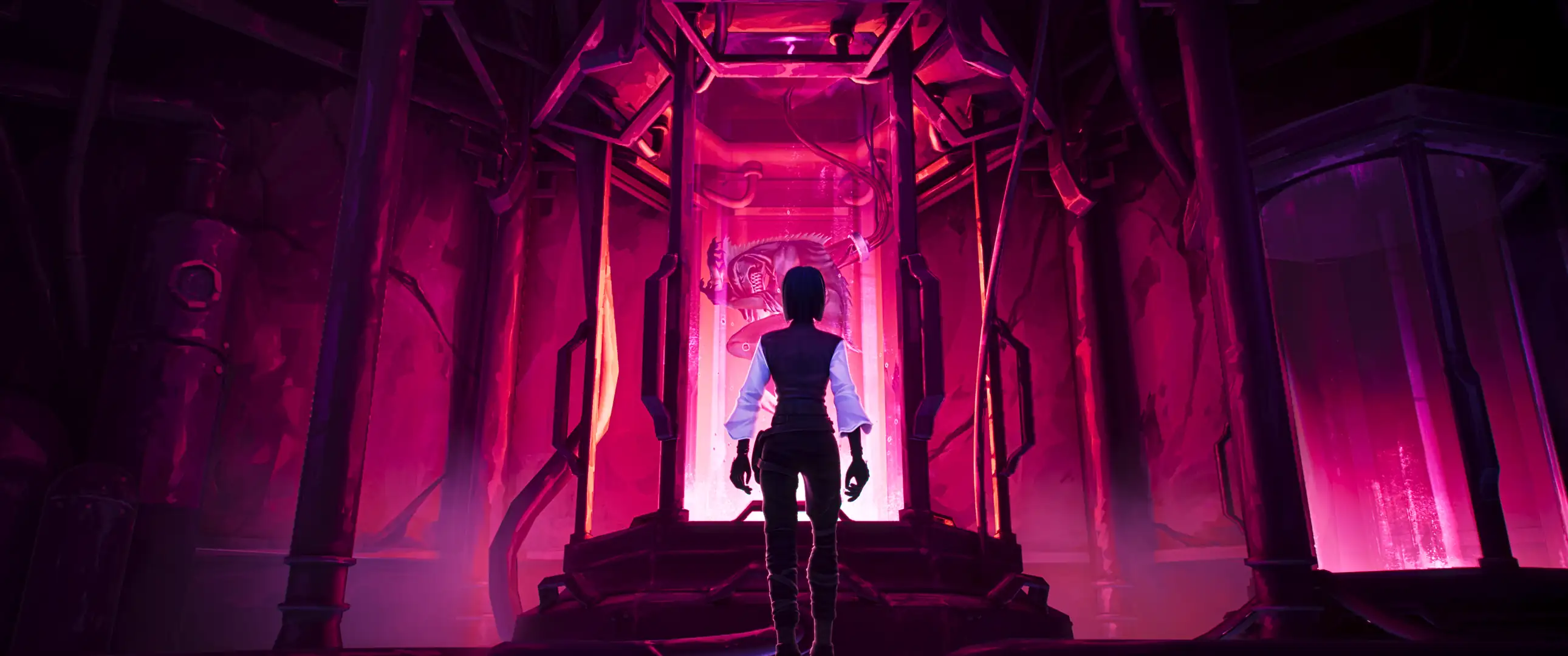
For the post-clip adjustments, I first added Chromatic Aberration and Lens Distortion for a bit of camera imperfection, then Vignette to shift attention a bit more away from the corners of the screen.
before
after
post-clip result
There were a few shots that got a few special corrections in the Clip section.
One shot was the one from the monster's point of view from inside the tube. I used two Waviness effects to create an effect looking like moving water, each for different sizes of waves.

tube pov shot
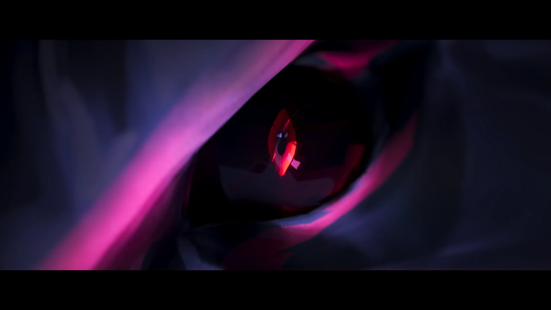
In the shot where the tube's water is being drained and the monster opens its eyes, I added a correction node with value and color adjustments to make it actually look underwater, since it admittedly didn't in the raw render.

raw render
I used a window mask to isolate the effect to the water area and keyframed it to match the shot.

water overlay in editor
I also wanted to add some flair to the title drop at the start. From here, I experimented a bit and landed on this setup.

title drop adjustments
Adding in the 2D VFX was relatively simple. The shots in need of drawing over were first sent to the 2D artist at full size to animate over, which solves any image alignment issues later on. I worked on the lookdev and colour grading while this was going on.
The finished animation clips were then sent to me with a transparent background so I could lay it on top of the original clip.

2d vfx clip
Afterwards, the clips just needed to be synced to the rest of the scene by matching the frame numbers.
From here, I applied a Screen blend mode and lowered the opacity slightly. Then, I looked to see if the clip was blending in well. If it wasn't, I adjusted the value and colour offset by feel to match it.
Truth be told, there wasn't much needed to be done here.

2d vfx before adjustments

2d vfx after adjustments
conclusion.
My team worked immensely hard to bring Crimson Heist to life. This project has given me an invaluable amount of experience in working in a team as a technical artist, and solving the technical challenges I faced along the way.
Thank you for taking the time to read this project breakdown!
Make sure to check out the artstation post.